
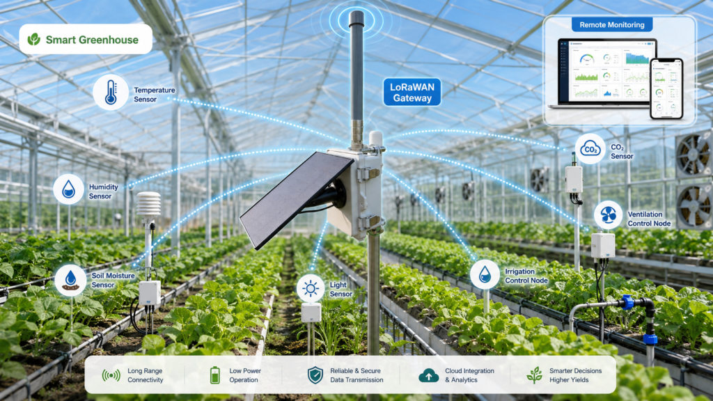
Smart greenhouses increasingly depend on wireless sensors and controllers to monitor temperature, humidity, soil or substrate moisture, CO₂ levels, irrigation status, vents, lighting, pumps, and other equipment. LoRaWAN is well suited to many of these applications because the devices usually transmit small amounts of data and may need to operate with limited power. Greenhouse monitoring and automation are also recognized smart-agriculture use cases within the wider LoRa ecosystem.
However, installing LoRaWAN inside a greenhouse is not the same as placing a sensor in an open field.
A greenhouse may look transparent to people, but from an RF perspective it can be a complex structure containing metal frames, pipes, cables, motors, irrigation equipment, dense crops, wet foliage, tanks, machinery, and rows of changing vegetation. All of these can influence how radio waves travel between a sensor and a gateway.
That is why selecting a LoRaWAN greenhouse antenna should not be reduced to choosing the highest dBi number or matching an antenna to 868 MHz or 915 MHz. Reliable greenhouse communication depends on the complete RF environment: antenna type, frequency, polarization, installation height, device enclosure, gateway location, crop density, cable loss, and the final assembled product.
Why Is a Greenhouse a Difficult RF Environment?
Greenhouse coverage often changes more than engineers expect because the environment is not static.
Metal frames can reflect or block part of the RF energy. Irrigation pipes, electrical cabinets, motors, fans, heating equipment, grow racks, and other conductive structures can create additional reflections and shadowed areas.
Plants introduce another variable. As a crop grows, the amount of vegetation between a sensor and gateway changes. Leaves and stems contain water, so a dense or wet crop can create a different propagation environment from the same greenhouse immediately after planting.
This means a network that performs well when the greenhouse is relatively empty should not automatically be assumed to perform identically after the crop reaches full height.
The problem becomes more complicated in facilities divided into multiple growing zones. A gateway may have a clear path to one section but several rows of plants and metal structures between it and another.
Instead of treating the greenhouse as one open rectangular space, it is usually more useful to think of it as a collection of RF zones.
Understand the LoRaWAN Network Before Selecting the Antenna
In a typical greenhouse LoRaWAN system, distributed end devices send data to one or more gateways. The gateway then connects to the network server or cloud platform through Ethernet, cellular, Wi-Fi, or another backhaul.
Possible greenhouse end devices include:
- temperature and humidity sensors;
- soil or substrate moisture sensors;
- CO₂ sensors;
- irrigation controllers;
- tank or water-level sensors;
- vent and window controllers;
- weather stations;
- energy meters;
- lighting controllers;
- pest or disease monitoring devices.
The antenna requirements of these devices can be very different from those of the gateway.
A compact sensor may need a small PCB, FPC, spring, or external antenna integrated into a plastic enclosure. A gateway installed on a greenhouse roof, service building, or elevated pole may be better suited to an external fiberglass antenna.
This distinction matters. The question is not simply, “Which LoRa antenna is best?” It is “Which antenna is appropriate for this device, at this position, in this RF environment?”
RFLink’s guide to internal versus external antennas explains this broader design tradeoff. Internal antennas provide better mechanical integration, while external antennas can offer greater installation flexibility and are usually less affected by internal components.
1. Start With the Correct Frequency Band
The antenna must first support the frequency range used by the LoRa or LoRaWAN device.
Do not assume that every international project should use the same “LoRa frequency.” LoRaWAN regional operating parameters differ between regulatory regions, so the module, network configuration, antenna bandwidth, and local regulatory requirements must be considered together. The current LoRa Alliance Regional Parameters continue to define different plans for different regions.
For example, RFLink currently offers an 868 MHz LoRa fiberglass antenna series covering 862–870 MHz and a 915 MHz LoRa fiberglass antenna series covering 900–930 MHz. These are separate frequency solutions rather than interchangeable labels.
For equipment manufacturers selling into several markets, frequency planning should therefore happen early in product development.
2. Do Not Hide an Antenna Behind Metal
Metal is one of the most common reasons a greenhouse LoRa node performs well during bench testing but poorly after installation.
Consider a controller mounted inside a stainless-steel or painted-metal enclosure. The LoRa module may be operating correctly, and the antenna may show acceptable free-space data, but once everything is installed inside the cabinet, the enclosure can severely alter the RF path.
In this situation, moving the antenna outside the metal enclosure is often more important than simply replacing a lower-gain antenna with a higher-gain model.
Options may include:
- a bulkhead-mounted external antenna;
- a waterproof rubber antenna;
- a cable-mounted antenna positioned outside the enclosure;
- an external fiberglass antenna for a fixed gateway or central controller.
The same principle applies to sensors mounted behind metal grow racks, structural columns, or equipment housings.
3. Treat Embedded Sensor Antennas as Part of the Final Device
Internal LoRa antennas require a different design approach.
A PCB or FPC antenna cannot be evaluated as an isolated component. Its behavior depends on the PCB ground, available clearance, battery, enclosure, cable routing, mounting material, and nearby components.
RFLink’s articles on VSWR and antenna impedance explain why an antenna that looks acceptable before integration can change after it is installed in the final product.
For a compact greenhouse sensor, engineers should evaluate at least:
- antenna clearance;
- PCB ground dimensions;
- distance from batteries and displays;
- distance from screws, brackets, or metal mounting plates;
- enclosure material;
- cable position, if an FPC antenna uses a coaxial feed;
- final installation orientation.
This is especially important for small battery-powered sensors where the antenna is forced into a limited area.
If the product structure cannot accommodate a standard antenna without excessive detuning, a custom antenna solution may be more appropriate than repeatedly changing modules or increasing transmit power. RFLink’s current custom-development process includes requirement review, RF design, tuning, prototype validation, and production support.
4. Put the Gateway Where the Network Can Actually “See” It
Gateway placement can have a larger effect on greenhouse coverage than a small difference in antenna gain.
A gateway installed at bench height may be surrounded by plants, irrigation equipment, tanks, and workers. Raising the antenna can reduce the amount of material immediately blocking the RF path.
Possible positions include:
- above the main crop canopy;
- on a central structural column;
- on a service building;
- near the roof structure;
- outside the greenhouse with suitable coverage into the growing area;
- at a position covering several adjacent greenhouse sections.
The best location depends on the building geometry.
For a single long greenhouse, a central position may reduce the maximum path length to the end nodes. For several adjacent houses, an elevated position between them may provide a better overall geometry.
There is no universal mounting height. The practical objective is to reduce unnecessary obstructions while keeping cable loss, maintenance, lightning protection, structural mounting, and outdoor exposure under control.
5. Higher Gain Is Not Automatically Better
A common assumption is that the highest-gain antenna will always produce the strongest greenhouse network.
That is too simple.
Antenna gain describes how RF energy is distributed. Increasing gain in an omnidirectional antenna commonly changes the radiation pattern rather than creating extra RF power. A higher-gain vertical antenna can concentrate more energy toward the horizon while narrowing vertical coverage. RFLink’s antenna gain guide discusses this tradeoff.
Imagine a gateway mounted high above the crop while many sensors are installed almost directly below it. An extremely narrow vertical radiation pattern may not be ideal for that geometry.
On the other hand, a wider, relatively flat greenhouse site with distant nodes at similar elevations may benefit from a different gain pattern.
Therefore, gateway antenna gain should be selected together with:
- gateway height;
- distance to nodes;
- greenhouse dimensions;
- vertical separation between gateway and sensors;
- building geometry;
- required coverage direction.
Judge the radiation pattern, not only the dBi number.
6. Keep Antenna Polarization and Device Orientation in Mind
Many fiberglass and rubber LoRa antennas use linear polarization and are normally intended to operate in a defined orientation.
If a vertically polarized gateway antenna communicates with fixed sensors whose antennas are installed in a compatible orientation, polarization loss can be reduced.
Problems arise when a product is mounted differently at different sites. One installer may place a sensor upright; another may lay the same unit horizontally on an irrigation pipe.
RFLink’s antenna polarization guide explains that polarization mismatch can reduce received signal strength even when both antennas operate at the correct frequency.
For mass-deployed greenhouse sensors, mechanical design should ideally encourage a repeatable installation orientation.
7. Crop Growth Should Be Included in Coverage Testing
One of the easiest greenhouse testing mistakes is commissioning the network before the crop reaches a representative growth stage.
A better validation process compares several realistic operating conditions.
For example:
Stage A: Empty or newly planted greenhouse
Measure basic connectivity and identify obvious structural dead zones.
Stage B: Representative crop height
Repeat measurements when the canopy has developed.
Stage C: Wet operating condition
Evaluate the network during or after irrigation where practical, particularly in dense crop areas.
Stage D: Full equipment operation
Check communication while pumps, motors, fans, lighting systems, and other electrical equipment are operating.
The purpose is not to create one impressive maximum-distance test. It is to determine whether the network remains usable in the conditions it will actually experience.
RSSI and SNR can be useful measurements, but they should be evaluated together with packet delivery reliability, retransmissions, gateway reception diversity, and application-level behavior.
8. Avoid Unnecessary Coaxial Cable Loss
Installing an antenna higher can improve the RF path, but a long coaxial cable adds loss.
This creates an engineering tradeoff.
Moving an antenna five meters higher but adding a long run of unsuitable cable may give back part of the RF benefit through feeder loss. Long outdoor cables also introduce additional connectors and weather-sealing points.
Whenever possible:
- keep the RF cable reasonably short;
- select cable based on loss at the operating frequency;
- minimize unnecessary adapters;
- waterproof outdoor connections correctly;
- route the cable away from potential mechanical damage;
- consider locating the gateway radio closer to the antenna and extending Ethernet or another backhaul instead.
The exact architecture depends on the greenhouse installation.
9. Node Antenna and Gateway Antenna Should Not Be Chosen the Same Way
| Device | Typical RF priority | Possible antenna approach |
|---|---|---|
| Compact environmental sensor | Low power, compact size, repeatable installation | PCB, FPC, spring, or small external antenna |
| Irrigation controller | Outdoor durability, cabinet penetration | External waterproof antenna |
| Metal equipment cabinet | Signal must leave conductive enclosure | Bulkhead or cable-mounted external antenna |
| Fixed greenhouse gateway | Coverage and durable installation | External fiberglass antenna |
| Central outdoor gateway | Wide-area coverage between greenhouse blocks | Elevated fiberglass antenna |
The table is not a universal specification. It is a starting point for system design.
Common LoRaWAN Greenhouse Antenna Mistakes
Several recurring mistakes can cause weak coverage:
- Selecting an antenna only by dBi.
- Installing an internal antenna directly beside metal.
- Placing the gateway below a dense mature crop canopy.
- Ignoring polarization and sensor orientation.
- Using an 868 MHz and 915 MHz antenna interchangeably without checking bandwidth.
- Testing only in an empty greenhouse.
- Using excessively long coaxial cables.
- Assuming good VSWR guarantees good real-world coverage.
- Changing transmit settings before investigating the antenna installation.
Antenna performance should be treated as a system-level problem.
FAQ
Do metal greenhouse frames affect LoRaWAN?
They can. Metal structures may block, reflect, or redirect RF energy, creating different coverage conditions across the greenhouse. The effect depends on geometry, antenna placement, frequency, and the position of the devices.
Should greenhouse LoRa sensors use internal or external antennas?
Either can work. Internal antennas are useful for compact integrated sensors, while external antennas provide more installation freedom. The enclosure, mounting environment, available space, and required coverage should determine the choice.
Where should a greenhouse LoRaWAN gateway antenna be installed?
It should generally be positioned where unnecessary obstructions are minimized and where it has useful geometry toward the target sensors. In many cases this means mounting above the crop canopy or in an elevated central position.
Is an 8 dBi LoRa antenna better than a 3 or 5 dBi antenna?
Not automatically. Different gain levels produce different radiation patterns. Gateway height, node distribution, terrain or building geometry, and vertical coverage all matter.
Can I use the same LoRa antenna worldwide?
Do not assume so. LoRaWAN frequency plans vary by region. Confirm the regulatory region, module configuration, network plan, and antenna operating bandwidth.
Conclusion
Reliable LoRaWAN coverage in a smart greenhouse depends on much more than the radio module.
Metal greenhouse structures, crop density, wet vegetation, equipment placement, sensor enclosure design, gateway height, antenna polarization, cable loss, and the radiation pattern all influence the final link.
The most effective approach is to design the antenna system around the complete greenhouse rather than selecting a component from a datasheet and hoping it behaves the same after installation.
For manufacturers developing greenhouse sensors, environmental controllers, irrigation terminals, or LoRaWAN gateways, RFLink can support antenna selection and custom RF antenna development when standard antennas cannot meet the required frequency, size, installation, or integration conditions.