
Wireless communication that works well in an open field can behave very differently once a robot enters a mature cornfield. Tall stalks, broad leaves, high moisture content, changing robot orientation, and a low antenna installation height can turn a seemingly straightforward link into a highly variable RF channel.
That was the central challenge in this custom antenna project. The customer was developing a smart agriculture robot that needed stable wireless video and data transmission while moving between rows of tall corn. Several standard antennas had already been tested, including higher-gain models, lower-gain models, and antennas with adjusted radiation patterns. None delivered sufficiently stable performance in the real operating environment.
The project therefore required more than another product substitution. RFLink approached it as a paired custom antenna solution for the complete wireless link: one antenna for the base-station side and another for the mobile robot terminal. The final solution included a 4 dBi base-station antenna and a compact 2 dBi terminal antenna designed with polarization stability, installation constraints, and vibration resistance in mind.
Project at a Glance
| Item | Project Information |
|---|---|
| Application | Smart agriculture robot operating in a cornfield |
| Main communication need | Stable wireless video and data transmission while the robot moves |
| Environmental challenge | Tall, dense corn plants obstructing and scattering the RF signal |
| Previous attempts | Multiple standard antennas with different gain levels and radiation-pattern adjustments |
| Main engineering priorities | Reduce polarization-related link variation, fit the robot structure, reduce size, and improve vibration resistance |
| Delivered solution | 4 dBi antenna for the base-station side and 2 dBi antenna for the robot terminal |
| Validation result | The customer tested the paired solution and reported satisfactory performance |
Why a Cornfield Is a Difficult RF Environment
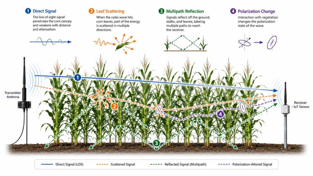
A cornfield is not simply an open outdoor area with a few obstacles. Once the crop reaches full height, the radio path may pass through a dense, irregular, and moisture-rich layer of leaves and stalks. The propagation environment also changes as the robot moves from one row to another.
Several effects can occur at the same time.
Vegetation Attenuation
Leaves and stalks absorb and scatter part of the transmitted energy. The severity depends on frequency, crop density, plant moisture, propagation distance, antenna height, and the geometry of the crop rows. A link budget that appears adequate in free space may therefore have much less margin inside the field.
Multipath and Polarization Changes
The direct signal may be weakened, while reflected and scattered components arrive from different directions. Those components can have different phases and polarization content. As a result, the receiving antenna may not see the same clean polarization relationship that existed during bench testing or an open-field test.
This is why antenna polarization becomes an important system variable. The practical issue is not that every corn leaf rotates the signal by a fixed angle. Rather, the crop canopy creates a changing combination of attenuation, scattering, reflection, and polarization mismatch. The usable received signal can vary even when transmitter power and nominal antenna gain remain unchanged.
Published cornfield measurements support this engineering concern. A 2024 propagation study at 0.9 GHz and 2.4 GHz found that received signal levels were influenced by the vegetation, antenna polarization, and the relative heights of the transmitting and receiving antennas.
Continuous Robot Movement
A mobile robot changes position, heading, tilt, and distance from the base station. Its antenna may also move relative to the metal frame, battery, control electronics, camera, and other structural parts. These changes can alter the radiation pattern and the polarization alignment seen by the remote antenna.
A stationary test therefore cannot fully represent the operating condition. The antenna must tolerate a range of orientations instead of performing well only when the robot faces one direction.
Low Installation Height and Mechanical Constraints
Agricultural robots usually cannot place every antenna high above the crop. The antenna has to fit the real machine, avoid interfering with mechanical movement, survive repeated vibration, and remain practical for assembly and maintenance.
These constraints make RF and mechanical design inseparable. A mechanically convenient location may be poor for radiation. A larger antenna may improve one RF parameter but become unsuitable for the terminal structure. A flexible mounting approach may reduce mechanical stress but allow excessive antenna movement. The final design must balance all of these factors.
Why Changing Antenna Gain Did Not Solve the Problem
The customer had already tested both high-gain and low-gain antennas. This was a reasonable troubleshooting step, but it did not address the dominant failure mechanism.
Higher Gain Is Not a Universal Cure
Antenna gain describes how radiation is concentrated in particular directions. It does not create additional transmitter power, remove crop attenuation, or automatically correct polarization mismatch. Depending on the antenna structure, increasing gain can also narrow coverage in one plane.
For a moving robot, a narrower useful elevation region may make the link more sensitive to changes in height, tilt, terrain, and orientation. The nominal dBi value may look better on a datasheet while the field link becomes less consistent.
This is the same reason that antenna gain should never be evaluated as an isolated indicator of communication distance. Actual performance depends on the complete link budget, radiation pattern, polarization, installation, obstacles, interference, cable loss, radio output power, and receiver sensitivity.
Lower Gain Alone Does Not Fix Polarization Mismatch
A lower-gain antenna may provide broader angular coverage in some designs, but that does not guarantee stable reception through a dense crop canopy. If the useful received field is strongly affected by changing polarization components and multipath, simply replacing one standard antenna with another may leave the root cause unchanged.
Radiation-Pattern Optimization Must Match the Real Motion
Adjusting the radiation pattern can improve coverage in a defined direction. However, a pattern optimized for a fixed installation may not suit a robot that is continuously turning, pitching, and moving between crop rows.
The choice between omnidirectional and directional antennas must therefore be based on the actual movement envelope and base-station geometry. The design target is not the most impressive free-space pattern. It is the most useful pattern after the antenna is installed on the real robot and operated inside the real field.
Optimizing Only One End Leaves Half the Link Uncontrolled
The base station and robot terminal form one RF system. Improving only the robot antenna may not produce a stable result if the base-station antenna has an unsuitable pattern, polarization response, installation height, or coverage region. The reverse is also true.
For this project, RFLink treated the two endpoints as a coordinated pair rather than two unrelated catalogue items.
Engineering Objective 1: Improve Robustness Against Polarization Variation
The first priority was to reduce the link sensitivity to polarization changes caused by the crop environment and robot movement.
RFLink’s RF engineers developed a proprietary antenna structure for this operating condition. The design was optimized to preserve a more usable coupling relationship as the terminal moved and the propagation channel changed. Because the detailed radiating structure is part of the project-specific design, it is not disclosed in this case study.
The important engineering lesson is that polarization performance should be considered at the system level. A nominal polarization label on a datasheet describes a controlled antenna characteristic. It does not fully predict what happens after the antenna is installed on a moving machine and the signal travels through dense vegetation.
The design process therefore focused on the combination of:
- the antenna’s installed radiation behavior;
- the expected robot orientations;
- the base-station position and coverage area;
- the surrounding crop structure;
- nearby mechanical and electronic components; and
- the interaction between the two custom antennas.
This changed the project from a simple gain comparison into a device-and-environment optimization task.
Engineering Objective 2: Build a Compact, Vibration-Resistant Robot Antenna
The second priority was mechanical integration. The terminal antenna had to fit the smart agriculture robot without creating an oversized external structure or becoming vulnerable to continuous vibration.
RFLink optimized the antenna dimensions and mechanical arrangement to reduce the overall size while maintaining the required RF behavior. The structure was also adapted to improve resistance to movement and vibration in the robot application.
This matters because vibration can affect more than physical durability. Repeated movement may change antenna orientation, cable routing, connector loading, spacing from nearby metal, or the relationship between the antenna and its mounting structure. Even small mechanical changes can produce RF variation when the original design has little margin.
The terminal antenna was therefore developed as an integrated component of the robot rather than an accessory added after the mechanical design was complete. This device-level approach is similar to other rugged projects where RF performance, compact space, sealing, and vibration must be considered together, such as RFLink’s custom battery-pack antenna case study.
The Paired Antenna Solution
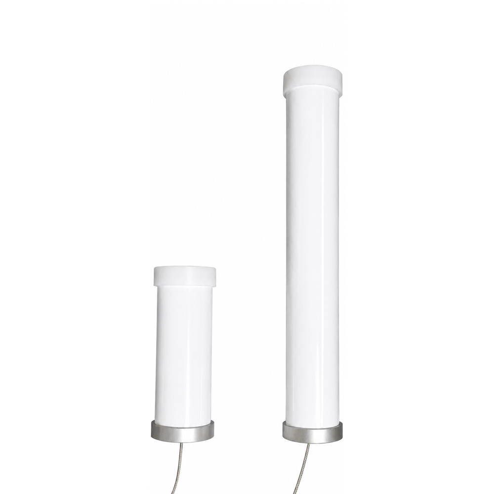
After evaluating the failure mechanism and the installation requirements, RFLink completed two custom designs.
4 dBi Base-Station Antenna
The base-station side used a 4 dBi design. The target was a practical balance between useful field coverage and directional concentration rather than maximizing the gain number.
The base-station antenna had to support communication across the robot’s working area while cooperating with the polarization and pattern characteristics of the terminal antenna. Its role was not merely to transmit more strongly. It had to provide an appropriate receiving and transmitting response for the changing path through the cornfield.
2 dBi Robot-Terminal Antenna
The mobile terminal used a 2 dBi design. This gain target supported the project’s compactness and movement-tolerance objectives while allowing the engineers to focus on the installed radiation behavior and proprietary polarization-oriented structure.
The terminal design also addressed the robot’s size and vibration requirements. Instead of selecting a larger standard antenna only because it had a higher catalogue gain, the project prioritized consistent operation in the intended installation.
Why the Two Different Gain Targets Made Sense
The two endpoints had different jobs.
The base station was relatively fixed and could use a moderate-gain design to shape coverage over the operating area. The robot terminal was mobile, mechanically constrained, and exposed to continuous orientation changes. Its design required a different balance of gain, angular coverage, size, and mechanical stability.
Using 4 dBi at the base-station side and 2 dBi at the terminal side was therefore not a simple “strong antenna plus weak antenna” combination. It was a coordinated allocation of RF and mechanical characteristics according to the role of each endpoint.
Customer Testing and Project Outcome
RFLink delivered both customized antennas to the customer for testing as a complete pair. The customer evaluated the base-station and terminal designs in the intended application and was satisfied with the result.
No unsupported distance, throughput, RSSI, packet-loss, or video-frame-rate figures are included in this case study. The confirmed outcome is that the paired custom solution met the customer’s practical test expectations more successfully than the previously evaluated standard antennas.
The project demonstrates why field performance cannot always be improved by repeatedly switching between standard high-gain and low-gain models. When the dominant problems involve polarization mismatch, dynamic multipath, device movement, mechanical integration, and endpoint interaction, the correct solution may require a custom design for the complete RF link.
Five Engineering Lessons from This Agricultural Robot Project
1. Identify the Failure Mechanism Before Selecting Gain
A weak or unstable link does not automatically mean the antenna needs more gain. Engineers should first determine whether the main limitation is path loss, polarization mismatch, pattern nulls, installation detuning, interference, cable loss, receiver performance, or a combination of factors.
2. Test in the Actual Crop Environment
Open-field testing is useful, but it may not represent mature crops. Crop height, moisture, row direction, antenna height, and robot route can all influence propagation. Validation should include the intended field condition whenever possible.
3. Design Both Ends of a Critical Link Together
A base station and a mobile terminal are one communication system. Coordinated antenna design can be more effective than optimizing either endpoint independently.
4. Treat Mechanical Stability as Part of RF Stability
Antenna movement, cable displacement, connector stress, and changing spacing from metal can all affect RF behavior. A vibration-resistant structure helps protect both mechanical reliability and repeatable antenna performance.
5. Optimize for Installed Performance, Not the Datasheet Number
Free-space gain and VSWR are valuable parameters, but they do not describe the complete installed system. The final evaluation should include the actual enclosure, mounting location, nearby components, cable routing, motion, and operating environment.
Frequently Asked Questions
Why did the high-gain antennas fail to stabilize the robot’s video link?
Higher gain did not remove vegetation loss, dynamic multipath, or polarization mismatch. It may also have concentrated radiation in a way that was less tolerant of robot tilt and movement. The project required a structure and pattern designed for the real channel, not simply a larger dBi value.
Does corn always rotate antenna polarization?
It is more accurate to say that a dense corn canopy can attenuate, reflect, and scatter radio waves, producing received components with changing amplitude, phase, direction, and polarization content. The effect depends on frequency, crop condition, geometry, and antenna placement; it is not a fixed rotation applied by every plant.
Why was the base-station antenna 4 dBi while the robot antenna was 2 dBi?
The base station and robot had different installation and coverage requirements. The fixed side could use moderate gain to support the working area, while the mobile side needed a compact design with greater tolerance to changing orientation and vibration. The values were selected as part of a paired system design.
Can one standard antenna model be used at both ends?
Sometimes it can, but not automatically. If the two endpoints have different mounting heights, structures, motion, coverage requirements, or nearby materials, separate antenna designs may provide a better system result.
What information is needed to develop a custom antenna for an agricultural robot?
Useful inputs include the frequency band and wireless protocol, radio output power and receiver sensitivity, required data or video performance, base-station location, robot route, crop type and height, antenna mounting area, nearby metal and electronics, cable and connector requirements, size limits, vibration conditions, environmental protection needs, and target validation method.
Conclusion
This cornfield robot project shows that reliable wireless transmission is not always a matter of choosing the antenna with the highest gain. The customer had already tested multiple high-gain, low-gain, and pattern-adjusted antennas without resolving the instability.
The successful direction was to address the real system problem: changing polarization conditions, crop-induced attenuation and multipath, mobile orientation, compact installation, vibration, and the interaction between the base station and terminal.
By developing a 4 dBi base-station antenna and a 2 dBi robot-terminal antenna as a coordinated custom solution, RFLink provided a design that the customer successfully validated in its application.
For agricultural robots, outdoor IoT equipment, and other mobile devices that cannot achieve stable performance with standard antennas, RFLink can review the complete RF environment and develop an antenna around the actual device structure and operating conditions. To start an evaluation, contact RFLink with your frequency band, installation drawing, mechanical limits, and target link requirements.