
A farm can use a correctly configured LoRaWAN gateway, a suitable frequency band, and properly matched field-node antennas and still experience unstable coverage. In many cases, the problem is not the radio module. It is the position of the gateway antenna.
A gateway antenna mounted beside a metal roof, below a crop canopy, behind a water tank, or at the end of a long lossy cable may provide much less useful coverage than its gain specification suggests. By contrast, a moderate-gain antenna installed in a clear and carefully selected location may serve a wider and more stable area.
Effective LoRaWAN gateway antenna placement requires more than choosing the highest point on a building. Engineers must consider antenna height, line-of-sight conditions, Fresnel-zone obstruction, cable loss, radiation pattern, nearby metal, node distribution, terrain, weather protection, and future changes to the farm.
This guide explains how these factors interact and provides a practical process for planning, installing, and validating a LoRaWAN gateway antenna in agricultural environments.
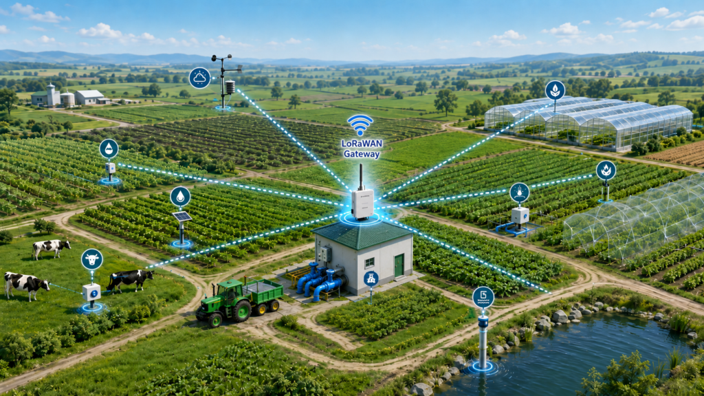
Why Gateway Placement Has So Much Influence
A LoRaWAN gateway is the central RF collection point for many distributed devices. A single gateway may need to communicate with soil sensors, valve controllers, weather stations, water meters, pump controllers, livestock trackers, storage monitors, and other nodes located in different directions.
The gateway therefore affects many links at the same time.
Improving one field-node installation helps one link. Improving the gateway antenna position may improve dozens or hundreds of links.
The gateway side also tends to have more installation flexibility. A soil sensor may need to remain close to the ground, but the gateway can often be moved to a mast, rooftop, pump-house pole, silo structure, or other elevated position.
This makes gateway placement one of the first variables to investigate when a farm network shows:
- Weak RSSI across many nodes
- Good performance near the gateway but poor performance in one zone
- Seasonal coverage changes
- Stable uplinks but unreliable downlinks
- Strong variation between nodes at similar distances
- Acceptable results during installation but poor results after crops mature
- Coverage that changes after a new building, tank, greenhouse, or machine is added
Antenna gain may be part of the solution, but it should not be the first or only variable changed.
Start with a Farm Coverage Map
Before selecting a mounting point, create a basic map of the farm.
The map does not need to be a complicated RF simulation at the early stage. It should show the physical relationships that affect the gateway.
Record:
- Planned gateway locations
- All required field-node locations
- Node height above ground
- Buildings and pump rooms
- Silos and water tanks
- Greenhouses
- Tree lines and woodland
- Mature crop height
- Orchard and vineyard row direction
- Slopes, hills, ditches, and valleys
- Metal fences and large irrigation structures
- High-voltage equipment, motors, and inverters
- Available power and backhaul connections
- Possible mast, pole, and rooftop positions
Then draw straight paths from each proposed gateway location to the required nodes.
The purpose is to identify which paths are clear and which paths cross major obstacles. Two gateway positions separated by only a short distance may produce very different coverage because one has a clear view over the field while the other is blocked by a roof, tree line, or storage building.
Distance should not be evaluated alone. A nearby node behind a dense obstruction may be more difficult to reach than a more distant node with a clear path.
RFLink’s guide on choosing a LoRa antenna for smart irrigation provides additional guidance for valve controllers, pump stations, metal cabinets, semi-buried boxes, and other field devices.
How High Should a LoRaWAN Gateway Antenna Be?
There is no universal mounting height that works for every farm.
The useful height depends on:
- Crop and tree height
- Terrain elevation
- Gateway-to-node distance
- Building and roof geometry
- Node installation height
- Antenna radiation pattern
- Cable route
- Mechanical and safety constraints
- Local grounding and lightning-protection requirements
The goal is not simply to install the antenna as high as possible. The goal is to achieve a clear and useful propagation path without creating excessive cable loss, mechanical risk, or unwanted coverage gaps.
Clear the Main Obstacles
A gateway antenna should ideally be above the most important nearby obstacles.
These may include:
- A pump-house roof
- A metal control cabinet
- A water tank
- A greenhouse frame
- Mature corn or other tall crops
- Orchard canopies
- A nearby building
- A tree line
- Agricultural machinery parked close to the gateway
Nearby obstacles are especially important because they can block or distort the antenna pattern before the signal reaches the wider field.
Raising the antenna by a small amount may provide a major improvement if it moves the antenna above a roof edge or crop canopy. Raising it further may provide little additional value if the path is already clear.
Consider the Fresnel Zone, Not Only the Visual Line
A visually clear line between the gateway and a node does not mean the entire radio path is unobstructed.
The radio signal occupies a three-dimensional region around the direct line. The first Fresnel zone is especially relevant when assessing whether terrain, roofs, crops, and other objects intrude into the main propagation area.
The current ITU-R P.526 recommendation includes the concepts of Fresnel ellipsoids, Fresnel zones, and diffraction around obstacles.
For farm deployment, the practical lesson is that an antenna path passing just above a roof, hill, or mature canopy may still experience loss even when the two antennas are technically visible to each other.
Possible responses include:
- Raising the gateway antenna
- Moving the gateway closer to the edge of a roof
- Relocating it away from a tank or wall
- Raising a difficult field-node antenna
- Moving a node slightly sideways
- Adding a second gateway for a blocked zone
A site survey should therefore look at the volume around the path, not only a thin line drawn on a map.
Choose the Mounting Location Before Choosing the Gain
One of the most common deployment mistakes is selecting a high-gain antenna first and then installing it wherever power and internet access are convenient.
The better sequence is:
- Map the required nodes.
- Identify promising gateway locations.
- Inspect propagation paths and obstacles.
- Determine the practical antenna height.
- Estimate the required cable route.
- Select the antenna pattern and gain.
- Test the complete installed system.
This order prevents an antenna specification from controlling the site design.
Pump-House Installation
A pump house often has power, Ethernet, cellular backhaul, and protection for gateway electronics. It can therefore be a convenient location.
However, the antenna should not automatically be mounted on the nearest wall.
Check whether:
- The roof blocks part of the field
- A water tank obstructs one direction
- Motors or inverters are located close to the cable
- The wall is metal
- The antenna can be extended to a pole above the roof
- The gateway can remain indoors while the antenna is outdoors
- The coaxial cable would become excessively long
Rooftop Installation
A rooftop can provide broad visibility, but the antenna position on the roof matters.
An antenna installed below a parapet, beside an air-conditioning unit, or close to a large metal roof surface may not produce the expected pattern.
Where practical, move the antenna away from immediate obstructions and use a secure mast or bracket suited to the local wind and weather conditions.
Field Mast Installation
A dedicated mast can provide excellent control over height and location. It may be placed near the center of the node distribution or at an elevated edge of the farm.
A field mast also introduces requirements for:
- Power delivery
- Backhaul
- Enclosure protection
- Grounding
- Lightning protection
- Wind loading
- Maintenance access
- Cable strain relief
- Protection from machinery and livestock
The best RF location is not automatically the best complete system location. RF performance, electrical safety, maintenance, and operating cost must be considered together.
Cable Loss Can Cancel the Benefit of Height
Moving an antenna higher usually requires a longer coaxial cable unless the gateway radio is moved with it.
Every cable introduces attenuation. Connectors, adapters, surge-protection devices, damaged cable sections, and water-contaminated interfaces can introduce additional loss or mismatch.
A useful simplified relationship is:
Net gateway antenna contribution = antenna gain − cable loss − connector and accessory losses
For example, adding several decibels of antenna gain does not create the expected improvement if a long cable and multiple connectors remove much of that benefit.
The exact cable loss depends on:
- Cable type
- Cable length
- Operating frequency
- Connector quality
- Adapter count
- Installation condition
- Cable bending and damage
- Water ingress
- Manufacturing tolerance
Cable loss generally increases with length and should be checked using the cable supplier’s data at the actual operating frequency.
Keep the RF Cable Short When Practical
Several design approaches can reduce cable loss:
- Mount the gateway closer to the antenna.
- Use Ethernet or fiber for the longer part of the route.
- Use Power over Ethernet when supported by the gateway.
- Select a lower-loss cable when a long RF route is unavoidable.
- Avoid unnecessary adapters.
- Use the correct connector type at both ends.
- Protect connectors from water and mechanical stress.
- Measure the assembled antenna-and-cable system before deployment.
The decision should not be reduced to “higher antenna” versus “shorter cable.” The correct choice is the combination that provides the best net link margin and acceptable mechanical reliability.
RFLink’s article What Is VSWR? explains how impedance mismatch and reflected energy can affect an antenna system. A low-loss cable cannot correct a badly matched antenna or water-damaged connector, so both attenuation and matching should be checked.
Should the Gateway Use 3 dBi, 5 dBi, or 8 dBi?
Higher gain is not automatically better.
An omnidirectional antenna normally achieves additional gain by concentrating more energy toward the horizon and reducing energy at other elevation angles. As gain increases, the vertical radiation pattern may become narrower.
This can be useful for a gateway serving distant nodes across relatively flat terrain. It can be less suitable when:
- Some nodes are very close to the mast
- The gateway is much higher than nearby nodes
- The terrain has large elevation changes
- Nodes are located on slopes
- The gateway must cover both a valley and a hill
- The installation requires useful coverage above or below the main horizontal plane
A moderate-gain antenna may provide a better balance between long-distance horizontal coverage and vertical coverage.
RFLink’s guide to antenna gain and radiation patterns explains why a larger dBi number should not be treated as a universal performance ranking.
RFLink currently lists:
The appropriate option depends on the required frequency, terrain, gateway height, node geometry, cable loss, and coverage pattern—not only the longest stated communication distance.
The antenna frequency must also match the project’s regional plan. The LoRa Alliance’s RP002-1.0.5 Regional Parameters describes LoRaWAN parameters for different regulatory regions. A project should confirm its operating region and channel plan before selecting the antenna and radio configuration.
Omnidirectional or Directional Gateway Antenna?
Use an Omnidirectional Antenna When Nodes Surround the Gateway
An omnidirectional antenna is usually appropriate when:
- Nodes are distributed in several directions
- The gateway is near the center of the farm
- The network layout may change
- New nodes may be added later
- The gateway serves multiple fields
- Simple installation is preferred
A vertically installed fiberglass omnidirectional antenna is a common choice for farm gateways because it can serve distributed nodes around the mounting point.
Consider a Directional Antenna for a Defined Coverage Zone
A directional or sector antenna may be useful when:
- Nearly all nodes are located in one direction
- The farm is long and narrow
- The gateway is installed at one end of a water channel
- One remote field requires focused coverage
- A hill or building blocks most other directions
- Unwanted interference is concentrated outside the target direction
A directional antenna must be aimed and secured carefully. If the bracket rotates or the mast moves, the target area may shift outside the strongest part of the pattern.
RFLink’s comparison of omnidirectional and directional antennas provides a broader explanation of their coverage differences.
One High-Gain Antenna Is Not Always Better Than Two Gateways
A very large or irregular farm may not have one location that provides clear paths to every required node.
In that case, adding another gateway can be more effective than forcing one high-gain antenna to cover:
- Opposite sides of a hill
- Separate valleys
- Multiple large buildings
- Distant greenhouses
- Fields divided by woodland
- Nodes with very different elevations
The LoRa Alliance’s 2026 network capacity optimization white paper discusses network-deployment approaches including gateway layers and macro-diversity.
For a farm, the same broad principle is useful: multiple well-placed reception points can improve resilience and reduce dependence on a single difficult propagation path.
Keep the Antenna Away from Immediate RF Obstructions
An outdoor rating does not mean an antenna can be placed against any outdoor structure.
Avoid mounting the antenna:
- Directly beside a large metal wall
- Below a metal roof edge
- Between steel structural members
- Behind a solar panel
- Immediately beside a water tank
- Inside a metal enclosure
- Very close to another transmitting antenna without an RF review
- Where the cable forces the antenna to tilt
- Where machinery can strike the antenna
- Where vegetation will grow around it
Nearby objects can distort the radiation pattern, change impedance, create reflections, and reduce coverage in specific directions.
The antenna should also maintain its intended polarization. If the gateway antenna is vertically polarized, field-node antennas should normally be installed with a compatible orientation.
Small differences in orientation may not break a strong link, but inconsistent installations can remove valuable margin from weak links.
Plan the Gateway Electronics and Antenna as One System
A gateway deployment includes more than the antenna.
The complete system may contain:
- LoRaWAN gateway radio
- Antenna
- Coaxial cable
- Connectors and adapters
- Surge-protection device
- Outdoor enclosure
- Power supply
- Ethernet, fiber, WiFi, or cellular backhaul
- Mast and mounting hardware
- Grounding and lightning-protection components
- Cable glands and seals
Each component can affect reliability.
A technically suitable antenna can still fail in service if:
- The connector is not sealed
- Water enters the coaxial cable
- The bracket rotates in strong wind
- The cable is sharply bent
- The cable gland allows tension on the RF connector
- The gateway overheats in an outdoor enclosure
- Backhaul is unstable
- The power supply cannot support the complete system
- Lightning or electrical transients damage the installation
Grounding, lightning protection, mast construction, and electrical work should follow applicable local requirements and be handled by qualified personnel. An antenna supplier can help with RF and mechanical interface requirements, but site safety requires local engineering responsibility.
A Practical Farm Gateway Test Method
A gateway should not be accepted based on one successful packet from the farthest point.
Use a repeatable test that reflects the application.
Step 1: Document the Installed System
Record:
- Gateway model
- Frequency plan
- Gateway position and elevation
- Antenna model and gain
- Antenna mounting height
- Antenna orientation
- Cable type and length
- Connector and adapter types
- Surge-protection components
- Node positions
- Node antenna types and heights
- Radio settings
- Weather and crop conditions
Without this record, future troubleshooting becomes guesswork.
Step 2: Establish Reference Nodes
Select several nodes representing different conditions:
- A nearby node
- A distant clear-path node
- A node behind crops
- A node behind a building or tree line
- A node at a different elevation
- A node in the most important control area
- A node close to the expected coverage boundary
Step 3: Record More Than RSSI
Measure:
- RSSI
- SNR
- Uplink delivery
- Downlink delivery when required
- Packet loss over time
- Performance at different data rates when relevant
- Variation across repeated transmissions
LoRa can sometimes decode packets below the apparent noise level, so RSSI should not be interpreted alone. A strong-looking individual packet also does not prove long-term reliability.
Step 4: Change One Variable at a Time
When comparing installation options, avoid changing the antenna, cable, height, radio settings, and gateway location simultaneously.
A useful sequence may be:
- Test the original installation.
- Raise the antenna without changing the antenna model.
- Test a shorter or lower-loss cable.
- Move the antenna away from the obstruction.
- Compare a different gain or radiation pattern.
- Add a second gateway if required.
This makes it possible to identify which change produces the improvement.
Step 5: Retest During the Difficult Season
A gateway installed during a bare-field period should be checked after crops reach mature height.
Also consider testing:
- After irrigation
- After rainfall
- During full orchard foliage
- After new structures are installed
- After moving pumps or machinery
- After changing the gateway enclosure or cable
The current ITU-R P.1411 recommendation addresses outdoor short-range propagation planning across a wide frequency range and reinforces the need to consider the actual propagation environment rather than relying only on free-space assumptions.
Gateway Placement Decision Table
| Farm condition | First placement approach | Main risk to check |
|---|---|---|
| Nodes spread around a central pump station | Elevated omnidirectional antenna | Roof, tanks, cable length and near-node coverage |
| Long, narrow irrigation channel | Directional or carefully selected omnidirectional antenna | Alignment, terrain and nodes outside the main beam |
| Large flat field with distributed nodes | Elevated moderate-gain omnidirectional antenna | Crop height and vertical beamwidth |
| Hilly farm | Test several gateway locations or use multiple gateways | Terrain diffraction and elevation differences |
| Orchard with repeated tree rows | Place gateway above canopy where practical | Cross-row obstruction and seasonal foliage |
| Separate fields divided by woodland | Consider more than one gateway | Excessive vegetation path and hidden zones |
| Gateway electronics must remain indoors | External antenna with short, suitable cable | Cable loss, connector sealing and wall obstruction |
| Remote solar-powered gateway | Mast-mounted integrated installation | Power budget, backhaul, weather and maintenance |
The table is a starting point, not a substitute for field measurement.
LoRaWAN Gateway Antenna Placement Checklist
Before final installation, confirm:
Coverage Geometry
- Are all required nodes shown on the site map?
- Are difficult paths identified?
- Is the gateway near the most useful elevation?
- Does the antenna clear nearby roofs, tanks, crops, and tree lines?
- Are near and far nodes both considered?
Antenna Selection
- Does the frequency match the regional plan?
- Is the antenna omnidirectional or directional for a clear reason?
- Is the selected gain compatible with the required vertical coverage?
- Is the antenna designed for the required outdoor environment?
- Is the antenna installed in the intended polarization?
Cable and Connectors
- Is the cable as short as reasonably practical?
- Is cable loss known at the operating frequency?
- Are unnecessary adapters removed?
- Are connectors correctly matched?
- Are outdoor interfaces sealed?
- Is there strain relief and a suitable drip loop?
- Has the complete assembly been checked for damage and mismatch?
Mechanical and Site Requirements
- Is the bracket suitable for local wind conditions?
- Can the antenna rotate or loosen?
- Is the installation protected from machinery and livestock?
- Is safe maintenance access available?
- Have grounding and lightning requirements been reviewed locally?
- Are power and backhaul reliable?
Validation
- Were RSSI, SNR, uplink, and downlink performance recorded?
- Were several representative nodes tested?
- Was testing repeated over time?
- Were variables changed individually?
- Is there enough margin for crop and weather changes?
- Is a second gateway needed for a blocked zone?
FAQ
What Is the Best Height for a Farm LoRaWAN Gateway Antenna?
There is no universal best height.
The antenna should be high enough to clear important nearby obstructions and improve the propagation path to required nodes. The final height must also account for cable loss, radiation pattern, mast safety, wind load, grounding, lightning protection, and maintenance.
Can I Place the LoRaWAN Gateway Indoors and the Antenna Outdoors?
Yes, provided the gateway supports an external antenna and the cable, connectors, sealing, impedance, and surge-protection arrangement are suitable.
Keep the RF cable reasonably short. For a long route, placing the gateway closer to the antenna and extending Ethernet, fiber, or another backhaul connection may provide lower RF loss.
Does a Longer Antenna Cable Reduce LoRaWAN Range?
A longer coaxial cable normally introduces more attenuation than a shorter cable of the same type.
The actual effect depends on cable construction, frequency, connectors, adapters, installation condition, and water ingress. Cable loss should be included in the complete link budget.
Is an 8 dBi Fiberglass Antenna Better Than a 5 dBi Antenna?
Not in every installation.
An 8 dBi antenna may support stronger low-elevation coverage across flat terrain, but its narrower vertical pattern may be less suitable for nearby nodes, slopes, valleys, or mixed elevations.
The choice should be based on the radiation pattern and site geometry.
Should a Farm Gateway Use an Omnidirectional Antenna?
An omnidirectional antenna is often appropriate when nodes are located around the gateway.
A directional or sector antenna may be more suitable when the required nodes occupy one defined direction, such as a long water channel or a separate remote field.
When Does a Farm Need a Second LoRaWAN Gateway?
A second gateway should be considered when one site cannot provide reliable paths to all critical nodes because of hills, buildings, woodland, separate fields, capacity requirements, or single-point-of-failure concerns.
Two carefully placed gateways may provide better coverage and resilience than one gateway using a higher-gain antenna from a compromised location.
Conclusion
Reliable agricultural LoRaWAN coverage starts with the geometry of the site.
Gateway antenna height matters because it can improve path clearance. Cable length matters because feeder loss can remove part of the benefit gained from a higher antenna. Gain matters because it changes the radiation pattern rather than creating free signal power. Omnidirectional and directional antennas serve different node layouts, and some farms are better served by more than one gateway.
The most effective LoRaWAN gateway antenna placement process is therefore:
- Map the nodes and obstacles.
- Select promising gateway locations.
- Clear nearby obstructions and consider the Fresnel zone.
- Keep cable loss under control.
- Match antenna gain and pattern to the actual terrain.
- Test representative links using RSSI, SNR, and packet delivery.
- Repeat testing after important seasonal or structural changes.
When a standard gateway antenna cannot meet the required frequency, gain, cable, connector, mounting, pattern, or environmental conditions, RFLink can provide custom antenna solutions based on the gateway structure and deployment environment.
To begin an engineering review, contact RFLink with the operating region, frequency band, gateway drawing, antenna height, cable requirement, node map, terrain information, and target coverage area.