
A LoRaWAN network may perform well when a field is bare and then become less stable after corn, fruit trees, vines, or other crops reach full growth. The gateway has not moved. The sensor nodes still use the same radio settings. Yet RSSI may fall, SNR may fluctuate, and packets may be lost in areas that previously looked safe on the coverage map.
The reason is simple: farmland is not a fixed radio environment. Crop height, leaf density, water content, row direction, soil moisture, machinery, and seasonal growth can all change the path between a node and a gateway. A link that was mostly line of sight during installation may later pass through a dense, wet canopy.
Understanding LoRa signal through vegetation helps system integrators make better decisions about gateway height, node placement, antenna type, polarization, and field testing. It also prevents a common mistake: trying to solve every coverage problem by selecting a higher-gain antenna without first identifying where the signal path is being obstructed.
Why an Open-Field Coverage Test Can Be Misleading
Many agricultural IoT projects are commissioned before crops reach their maximum height. During the early stage, the gateway may have a clear view across the field, and a technician may record strong RSSI and acceptable packet delivery at every planned node location.
Several weeks later, the same path may cross rows of stems, leaves, fruit, irrigation pipes, support wires, and wet soil. In an orchard, a signal may need to travel across multiple tree rows rather than along the open corridor between them. In a greenhouse, metal frames and wet plant material add another layer of reflection and attenuation.
This does not mean LoRaWAN is unsuitable for agriculture. It means the link budget and installation plan must reflect the mature environment, not only the empty field seen during installation.
The International Telecommunication Union addresses vegetation-related attenuation in ITU-R Recommendation P.833. The recommendation is a useful reminder that foliage loss depends on factors such as frequency, path length through vegetation, and the physical characteristics of the vegetation. A single universal “meters of range” claim cannot describe every farm.
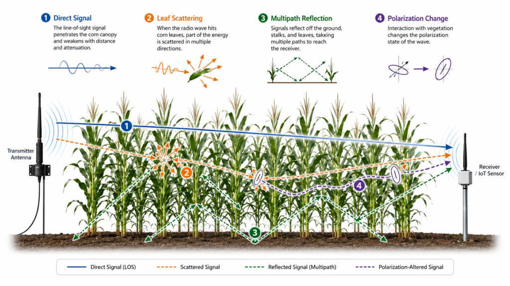
Four Ways Crops Change the Radio Path
Vegetation does not affect a LoRa link through only one mechanism. Several effects may occur at the same time.
1. Direct Signal Attenuation
The direct path is the most intuitive component. When a radio wave passes through stems, leaves, fruit, and branches, part of its energy is absorbed or redirected. The longer the path inside dense vegetation, the greater the potential loss.
A node at the far side of a mature cornfield may therefore experience more attenuation than a node at the same distance in an open field. The difference is not caused by distance alone. It is also affected by how much crop material occupies the path and how completely the canopy obstructs the main propagation area.
Water content matters because plant tissue contains water, and wet foliage can change the dielectric properties of the propagation environment. Conditions after rain, irrigation, or heavy dew may therefore differ from dry midday conditions.
The exact change depends on frequency, crop structure, moisture, and path geometry. It should be measured rather than assumed.
2. Leaf and Branch Scattering
Leaves and branches do not form a smooth wall. They create many irregular surfaces that can scatter part of the signal in different directions. Some scattered energy may still reach the receiving antenna, but it arrives through a less predictable path.
Scattering is one reason RSSI can vary even when the node and gateway remain stationary. Wind moves the leaves, irrigation changes moisture, and crop growth alters the number and orientation of objects in the propagation path.
The link may remain connected, but its margin can become less stable.
For low-data-rate agricultural sensors, occasional fading may not be noticeable if the system has sufficient link margin and suitable retry behavior. A marginal link, however, can shift from acceptable to unreliable as crop density increases.
3. Multipath Reflection
Agricultural sites contain many reflecting surfaces, including wet ground, metal irrigation pipes, machinery, greenhouse frames, water tanks, fences, support wires, and building walls.
A radio signal may reach the receiver through a direct path and several reflected paths. These components arrive with different delays and phases. Depending on the location, they may partially reinforce or partially cancel one another.
This creates local high-signal and low-signal areas that cannot be predicted from distance alone.
A node that performs poorly at one mounting point may improve after being moved a short distance vertically or horizontally. The improvement is not accidental. The new position changes the relationship between the direct and reflected components and may also reduce obstruction in the Fresnel zone.
4. Polarization Changes and Mismatch
A vertically polarized antenna ideally communicates with another vertically polarized antenna.
In a real crop environment, scattering and reflection can produce additional polarization components. If one antenna is tilted, mounted horizontally, bent against a cabinet, or installed inconsistently, polarization mismatch can further reduce the received signal.
Vegetation should not be described as simply rotating every signal by a fixed angle. The actual effect is more complex and depends on the propagation path.
The practical lesson is straightforward: maintain consistent antenna orientation, prevent cable tension from pulling small antennas sideways, and include polarization in the installation checklist.
RFLink’s guide to antenna polarization explains why antenna orientation and polarization alignment matter in wireless systems.
Crop Type, Growth Stage, and Row Direction Matter
A farm cannot be modeled as one generic block of foliage. Cornfields, vineyards, orchards, greenhouses, and low vegetable crops have very different structures.
Tall corn can create a dense vertical canopy during peak growth. Orchards create repeated rows of trunks, branches, and leaves, with relatively open corridors between them. Vineyards include posts and wires that may contribute to reflection. Greenhouses combine plants with metal frames, films or glass, water systems, and electrical equipment.
Row direction is especially important in orchards and vineyards.
A link that runs along a row may have a partially open corridor. A link that crosses many rows may pass through repeated layers of vegetation. Two nodes located at the same distance from a gateway can therefore have very different performance.
The crop growth stage also changes the environment. A network validated shortly after planting should not be considered fully validated for harvest season.
At minimum, the deployment team should identify the expected maximum crop height and canopy density and reserve additional link margin for seasonal change.
What Published Maize-Field Research Tells Us—and What It Does Not
A 2025 study titled Experimental Study on the Propagation Characteristics of LoRa Signals in Maize Fields examined 433 MHz LoRa propagation under dense maize conditions.
The researchers measured RSSI, SNR, packet loss, and propagation distance at different transmitter and receiver antenna heights. The study found that increasing antenna height generally improved signal quality and propagation range. It also reported greater propagation loss in maize fields than in open control environments.
This provides useful evidence for the practical value of antenna height and path clearance. However, the study’s numerical results should not be copied directly into every agricultural project.
The experiment used:
- A 433 MHz LoRa system
- Specific maize fields and crop conditions
- Particular transmitter and receiver heights
- Defined radio parameters
- Specific terrain and test locations
An 868 MHz or 915 MHz deployment using different antennas, spreading factors, receiver sensitivity, crop moisture, terrain, or node height may produce different results.
The correct conclusion is not that one fixed gateway height will cover every farm. The correct conclusion is that antenna height, crop obstruction, and real field geometry must be included in the deployment test plan.
Gateway Antenna Height: Clear the Canopy, Not Just the Cabinet
Raising the gateway antenna is often one of the most effective ways to improve agricultural coverage because it can reduce the amount of vegetation inside the main propagation path.
The goal is not simply to install the antenna above the gateway enclosure. The goal is to improve line-of-sight conditions and Fresnel-zone clearance toward the field nodes.
A gateway antenna mounted on a pump-house wall may still be blocked by a roof edge, water tank, trees, or mature crops. Moving the antenna to a mast, rooftop, or higher pole can be more valuable than increasing antenna gain while leaving the antenna at the same obstructed location.
Height must be balanced with practical constraints:
- A taller mast may require stronger mechanical support and a wind-load review.
- A longer coaxial cable introduces additional signal loss.
- Outdoor connectors require sealing and strain relief.
- Lightning protection and grounding should be coordinated with qualified local professionals.
- A high-gain omnidirectional antenna may have a narrower vertical beam, potentially weakening coverage for nodes located close to the mast or at substantially different elevations.
For a deeper discussion of gain and coverage shape, see What Is Antenna Gain?.
Field-Node Antenna Placement: Small Changes Can Protect Link Margin
Many agricultural field nodes are installed close to the ground because they measure soil conditions, valves, water meters, irrigation pressure, or water levels.
This is often unavoidable, but the antenna does not always need to remain at the same height as the sensing element.
A soil probe can stay in the soil while its radio antenna is mounted higher on a short post. A valve controller can use a cable-mounted external antenna above a semi-buried enclosure. A node inside a metal cabinet will often require an external antenna because the enclosure can shield the signal.
When planning node placement, check the following:
- Is the antenna below, inside, or above the mature crop canopy?
- Is it directly beside wet soil, water, or a metal pipe?
- Is the antenna hidden inside a metal or foil-lined enclosure?
- Can the antenna be moved to the edge or top of the housing?
- Is the antenna vertical and mechanically fixed?
- Could workers, livestock, machinery, or harvesting equipment damage the mounting point?
- Is the cable routed consistently across production units?
RFLink’s smart-irrigation LoRa antenna guide discusses metal cabinets, semi-buried enclosures, pump stations, cable routing, and outdoor antenna options in more detail.
Does Higher Antenna Gain Solve Vegetation Loss?
Not by itself.
A higher-gain antenna redistributes energy into a different radiation pattern. It may improve a link in a suitable direction, but it cannot remove crop absorption, clear an obstructed Fresnel zone, repair a damaged cable, or correct severe polarization mismatch.
For a farm with nodes distributed in multiple directions and at mixed distances, a moderate-gain omnidirectional fiberglass antenna may provide a practical balance between horizontal coverage and vertical beamwidth.
For a long, narrow field or a specific remote zone, a directional or sector antenna may be more appropriate.
The decision should be based on:
- Node distribution
- Terrain
- Gateway height
- Antenna radiation pattern
- Cable loss
- Required near and far coverage
- The complete link budget
RFLink provides published product options for 868 MHz fiberglass LoRa antennas and 915 MHz fiberglass LoRa antennas.
Product gain values should still be evaluated against the required coverage pattern and installation environment. They should not be treated as a universal communication-range guarantee.
Use RSSI, SNR, and Packet Delivery Together
A single RSSI screenshot is not enough to validate an agricultural LoRaWAN network.
RSSI indicates received signal power, while SNR describes the signal relative to the noise level. Packet delivery or packet error statistics show whether the link remains reliable over time.
A node may report an apparently usable RSSI but still suffer unstable delivery because of interference, fading, packet collisions, or insufficient link margin.
A practical field test should record:
- RSSI and SNR across repeated packets
- Uplink packet delivery over a meaningful test period
- Downlink success when the application requires remote control
- Results before and after irrigation or rainfall when relevant
- Results at different crop growth stages
- Gateway and node antenna heights
- Antenna type and gain
- Cable type, cable length, and connector configuration
- Spreading factor, bandwidth, transmit power, payload size, and retry settings
- Exact node locations
- Crop-row orientation
The purpose is not to produce one impressive maximum-distance result. The purpose is to identify the weakest required links and confirm that they maintain sufficient margin under realistic operating conditions.
A Seasonal Field-Test Method for Agricultural LoRaWAN
A reliable validation plan can be organized into six steps.
Step 1: Map the Mature Environment
Document the expected maximum crop height, row direction, tree density, slopes, buildings, tanks, power equipment, and metal structures.
Mark the node paths that cross the greatest amount of vegetation.
Step 2: Separate Gateway and Node Problems
Test the gateway antenna, coaxial cable, connectors, and mounting location independently. Then inspect the field nodes.
This prevents the team from replacing every node antenna when the actual problem is a lossy gateway cable or an obstructed mast location.
Step 3: Establish a Repeatable Baseline
Use the same radio settings, packet interval, payload, antenna orientation, and measurement duration at every test point.
Record multiple packets so that short-term fading does not dominate the conclusion.
Step 4: Test High-Risk Paths
Prioritize:
- Paths crossing multiple orchard rows
- Low-mounted nodes behind mature crops
- Semi-buried controllers
- Locations near pumps, motors, and inverters
- Nodes at the edge of the required coverage area
- Nodes hidden inside or beside metal structures
Step 5: Repeat After Environmental Change
Repeat the tests after the crop canopy has developed and, where practical, compare dry and wet conditions.
A deployment that works only during the easiest season has not been fully validated.
Step 6: Keep Margin for Production Variation
Prototype units are often installed carefully by engineers. Production units may include variations in cable routing, connector assembly, enclosure dimensions, mounting orientation, and antenna position.
The final design should tolerate reasonable manufacturing and installation variation.
Common Mistakes in Crop-Field LoRa Deployments
Testing Only Before the Crop Grows
This creates an optimistic coverage map and ignores the environment the network will face during the most important part of the growing season.
Mounting the Gateway Antenna Beside an Obstruction
A high-quality antenna installed below a roof edge, behind a water tank, or beside a metal wall may perform worse than a more modest antenna with a clearer propagation path.
Putting the Node Antenna Inside a Metal Box
Metal can shield radio signals. External or through-wall antenna placement is often necessary for long-range field controllers installed inside metal enclosures.
Using a Long Cable Without Checking Loss
Raising an antenna with a long, high-loss coaxial cable can cancel part of the benefit gained from additional height.
Cable type, length, connector count, and operating frequency all affect the result.
Selecting Gain Without Looking at the Radiation Pattern
Higher gain may narrow the vertical beam. This may be undesirable when nodes are located both near and far from the gateway or when the terrain is uneven.
Changing Several Variables at Once
If the team changes the antenna, cable, gateway height, spreading factor, and transmit power at the same time, it becomes difficult to identify which change actually solved the problem.
Change one major variable at a time and record the result.
When a Custom Antenna or Integration Review Helps
A standard antenna can work well when its frequency, connector, mounting structure, environmental suitability, and radiation pattern match the project.
Custom engineering becomes useful when the antenna must:
- Fit a special gateway or node enclosure
- Operate close to metal or wet materials
- Use a specific cable or connector
- Meet a defined mounting requirement
- Maintain performance across multiple regional frequency versions
- Provide a coverage pattern suited to the actual node layout
RFLink’s custom antenna solutions include requirement review, antenna design, RF simulation, tuning, prototype validation, and production support.
For an agricultural project, useful engineering inputs include:
- Target frequency band
- Gateway and node drawings
- Enclosure materials
- Antenna mounting height
- Cable and connector requirements
- Crop type and expected crop height
- Terrain information
- Node distribution map
- Target operating region
- Required communication directions and distances
FAQ
Can LoRa Signal Pass Through a Cornfield?
Yes. A LoRa link can operate through a crop environment, but dense corn may add attenuation and fading compared with an open field.
Reliability depends on frequency, antenna height, the length of the path through the crop, radio settings, installation quality, and available link margin.
Does Wet Foliage Reduce LoRa Range?
Wet foliage can change the propagation environment and may increase signal loss or variability.
The size of the effect depends on crop type, frequency, path geometry, and the amount of water. Testing before and after rain or irrigation is more reliable than applying one universal correction value.
Should a LoRaWAN Gateway Antenna Be Above the Crop Canopy?
Raising the gateway antenna above major obstructions will often improve path clearance.
The final height should also account for mast safety, wind load, cable loss, coverage geometry, local requirements, grounding, and lightning protection.
Should Every Field-Node Antenna Be Above the Canopy?
Not necessarily.
Some sensors must remain close to the ground, and short links may already have enough margin. However, raising only the antenna or moving it outside a buried or metal enclosure can substantially improve difficult links.
Is an 8 dBi Antenna Always Better Than a 3 or 5 dBi Antenna on a Farm?
No.
Higher gain changes the radiation pattern and may reduce vertical beamwidth. A moderate-gain omnidirectional antenna may be more suitable for nodes at mixed distances, while a higher-gain or directional antenna may suit a specific flat, narrow, or remote coverage zone.
How Often Should Agricultural LoRaWAN Coverage Be Retested?
Retest after major environmental or system changes, including:
- Significant crop growth
- Gateway relocation
- Antenna replacement
- New machinery or metal structures
- Enclosure changes
- Cable changes
- Radio-configuration updates
Seasonal testing is particularly useful when crop height and canopy density change substantially during the operating year.
Conclusion
LoRaWAN coverage in agriculture is shaped by more than distance.
Vegetation can attenuate the direct signal, scatter energy, create changing multipath conditions, and contribute to polarization mismatch. Crop height, moisture, row direction, gateway height, node placement, cable loss, and antenna radiation pattern all influence the final link.
The most reliable approach is to design for the mature crop environment, maintain consistent antenna orientation, improve propagation-path clearance before pursuing higher gain, and validate RSSI, SNR, and packet delivery across high-risk paths and changing seasons.
When evaluating LoRa signal through vegetation, there is no single antenna specification or universal distance value that can replace a properly planned field test.
If your project needs a gateway or node antenna adapted to a specific frequency, enclosure, cable, connector, mounting method, crop environment, or coverage pattern, contact RFLink with your site layout and device requirements for an initial engineering review.