
An outdoor WiFi network can look correct on paper and still perform badly after installation.
The AP is online.
The antenna supports the correct frequency.
VSWR may be acceptable.
Transmit power is configured correctly.
Users can even see the SSID.
Yet connections drop, throughput falls at certain locations, devices near the tower behave strangely, or coverage changes after vegetation grows.
In many cases, the problem is not the WiFi radio itself.
It is WiFi antenna placement for outdoor coverage.
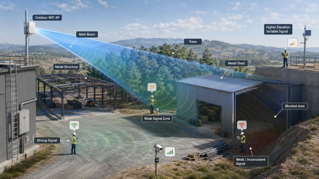
Antenna height, vertical beamwidth, downtilt, metal structures, trees, mounting surfaces, cable loss and client orientation can all change how the RF energy reaches the real service area.
This is why installation should be treated as part of antenna engineering.
1. A WiFi Antenna Does Not Radiate Like a Perfect Sphere
A common mental model shows an antenna sending an equal circular bubble of signal in every direction.
Real antennas do not behave that way.
Every antenna has a radiation pattern.
For an omnidirectional antenna, “omnidirectional” normally refers primarily to broad horizontal or azimuth coverage.
The vertical or elevation pattern can look very different.
A vertical dipole-type antenna may produce a doughnut-like three-dimensional pattern.
Higher-gain omnidirectional designs often make that doughnut flatter.
This is useful when users are far away at similar heights.
But it creates an important installation consequence:
The strongest signal may not be directly below the antenna.
2. Why an Antenna Can Be Too High
Increasing antenna height can improve path clearance.
That is why outdoor APs are often installed on rooftops, poles and towers.
But height should never be considered separately from beamwidth.
Imagine an antenna mounted 20 meters above the ground.
The target clients begin only a few meters away from the base of the pole.
If the antenna’s vertical beam is relatively narrow, the main lobe may travel outward above those nearby clients.
The users can then sit inside a weaker part of the radiation pattern.
The installer sees a tall antenna and assumes:
“Higher should mean stronger.”
But the real issue is geometry.
For every design, compare:
- antenna height;
- nearest client distance;
- farthest client distance;
- client height;
- elevation beamwidth;
- mechanical/electrical downtilt.
A lower antenna with a suitable pattern may outperform a higher antenna whose main beam does not intersect the required service area.
3. “Same Vertical Plane” Is Really a Beamwidth Problem
A useful field rule is sometimes expressed as:
“Keep the antenna and covered devices on the same vertical plane.”
The intention is helpful, but the RF concept should be expressed more precisely.
The clients do not need to be geometrically level with the AP.
They need to fall inside the antenna’s effective elevation coverage.
Consider a sector antenna installed on a building.
Its horizontal beam may cover 90° or another defined sector.
But it also has a vertical beam.
If the antenna points straight toward the horizon while the target area is below the mounting point, some form of downtilt may be necessary.
Mechanical downtilt physically angles the antenna.
Electrical downtilt changes the effective radiation pattern through antenna design or feed relationships.
The correct solution depends on the antenna system.
The important point is to design in three dimensions.
A top-down site plan shows only half the problem.
4. Near Coverage and Far Coverage Must Be Designed Together
Suppose an AP must serve users between 20 meters and 400 meters away.
Optimizing only for the 400-meter edge can produce poor coverage at 20–50 meters.
Conversely, using a very broad low-gain pattern may provide excellent near coverage but insufficient link margin farther away.
This creates a coverage tradeoff.
When planning the vertical pattern, identify:
- minimum service distance;
- maximum service distance;
- height of the AP;
- height of typical clients;
- terrain slope.
If the area is large enough, the better solution may be multiple APs rather than forcing one antenna pattern to cover every distance.
5. High Gain Changes More Than Range
RFLink’s antenna gain guide explains that gain represents directional concentration rather than additional generated power.
This is especially relevant for outdoor WiFi.
Changing from a moderate-gain antenna to a higher-gain antenna may:
- increase energy toward some directions;
- narrow beamwidth;
- change near-field service geometry;
- require more accurate alignment;
- change sensitivity to mounting angle.
Therefore:
Do not replace an antenna only because the new one has a larger dBi number.
Compare radiation patterns.
6. Metal Roofs and Steel Sheds Can Completely Change the RF Environment
Outdoor WiFi is often installed around:
- steel warehouses;
- corrugated iron sheds;
- shipping containers;
- machinery;
- silos;
- tanks;
- metal fences;
- solar structures;
- industrial racks.
Metal does not behave like empty air.
It can reflect RF energy and block transmission through certain paths.
For example, an AP may be installed under a metal roof because that location protects it from rain.
Mechanically, the position looks excellent.
RF-wise, it may be terrible.
The roof edge or wall can block the intended coverage direction or significantly change the antenna pattern.
Moving the antenna only a short distance so that it clears the roof line may produce a larger improvement than changing to a higher-gain model.
Avoid positions such as:
- directly behind a metal wall;
- deep below a corrugated roof edge;
- between large steel structures;
- immediately beside a metal tank;
- inside a metal enclosure unless the antenna is intentionally externalized.
Metal can also create multipath.
Reflections are not always bad—WiFi systems often operate in multipath environments—but severe, unstable or highly obstructed geometry can create local fading and inconsistent performance.
7. Trees Are Not Transparent to WiFi
Trees are another common outdoor coverage problem.
A single sparse branch may not destroy a WiFi link.
But a signal passing through many meters of dense foliage is a different situation.
Plant material contains water.
Leaves, branches and trunks can absorb, scatter and alter RF propagation.
The effect also changes with:
- vegetation density;
- tree species;
- moisture;
- rainfall;
- season;
- path length through foliage;
- operating frequency.
This explains why a wireless link installed successfully in winter may perform differently after full summer foliage develops.
A site survey should therefore ask:
What will the propagation path look like during the most difficult season?
Not only:
What does it look like today?
8. Avoid Looking Through More Vegetation Than Necessary
The geometry of vegetation matters.
Suppose an AP and client are on opposite sides of an orchard.
A low-mounted antenna may force the signal through dozens of trees.
Raising the AP may allow part of the main propagation path to clear the canopy.
Alternatively, relocating the AP sideways may allow the signal to travel along a road or open corridor instead of directly through dense vegetation.
This illustrates a general RF principle:
Improve the propagation path before trying to solve every problem with more gain.
A modest antenna with a clearer path can outperform a high-gain antenna behind heavy obstruction.
9. WiFi Frequency Changes the Environmental Sensitivity
A multi-band WiFi network may use 2.4 GHz and 5 GHz simultaneously.
These bands do not propagate identically.
The higher-frequency 5 GHz signal experiences greater free-space path loss than 2.4 GHz for the same distance and can be less forgiving through many obstructed paths.
That does not mean 2.4 GHz is “better WiFi.”
5 GHz offers important capacity and channel advantages.
The correct network may use both.
But coverage planning should recognize that a device connected at 2.4 GHz from one location may not have the same link margin at 5 GHz.
Do not assume one coverage map applies equally to every band.
10. Interference Can Look Like Weak Coverage
Not every WiFi problem is caused by attenuation.
Sometimes the signal level is adequate, but the channel is heavily occupied.
Possible sources include:
- neighboring WiFi networks;
- multiple APs configured on overlapping channels;
- industrial wireless equipment;
- large numbers of clients;
- other devices operating in shared spectrum.
Symptoms may include:
- strong RSSI but poor throughput;
- high latency;
- unstable performance during busy periods;
- good performance at night but poor daytime performance.
Increasing antenna gain does not automatically solve co-channel interference.
In fact, an omnidirectional high-gain antenna may receive more unwanted energy from distant sources in the same horizontal plane.
Directional coverage can sometimes help reduce energy received from unwanted directions, but proper WiFi channel planning remains necessary.
11. Antenna Polarization and Orientation Still Matter
Two compatible linear antennas generally perform best when their polarization orientations are appropriately aligned.
However, WiFi clients are not always fixed.
Phones rotate.
Tablets are carried in different directions.
Cameras may be installed horizontally or vertically.
Modern MIMO systems use multiple antenna elements partly to improve performance in complex multipath and orientation conditions.
For fixed outdoor equipment, installation consistency still matters.
If a WiFi bridge or industrial client uses a defined antenna orientation, installers should not arbitrarily rotate the antenna 90°.
RFLink’s antenna polarization guide explains this principle in more detail.
12. The AP Housing Can Change an Internal Antenna Pattern
For manufacturers developing an AP rather than simply installing an external antenna, the problem moves inside the product.
The final radiation pattern can be influenced by:
- plastic housing;
- metal frame;
- PCB;
- ground structure;
- heat sink;
- shielding;
- screws;
- cable routing;
- internal antenna spacing;
- reflector design.
RFLink’s current Internal Directional AP Antenna solutions are developed around this device-level relationship.
A directional AP antenna cannot simply be designed on a bench and then inserted into any housing.
The housing itself becomes part of the RF environment.
13. Cable Loss Can Undo the Benefit of Better Antenna Placement
An installer notices that a rooftop position gives much better line of sight.
The antenna is moved upward.
Then a long coaxial cable is added.
This creates a new problem.
Every RF cable introduces attenuation.
The amount depends on:
- frequency;
- cable construction;
- length;
- connectors;
- adapters;
- installation quality.
At WiFi frequencies, long feeder runs can become significant.
For many outdoor systems it is worth considering:
AP close to antenna + long Ethernet/PoE
rather than:
AP far away + long RF cable.
This is an architectural decision, not just a cable decision.
14. Rain Protection Should Not Create RF Obstruction
Outdoor equipment needs protection from weather.
But do not solve the mechanical problem by creating an RF problem.
For example, mounting an antenna completely beneath a metal canopy may keep it dry while destroying the desired coverage direction.
A better outdoor design may use:
- weather-rated AP enclosure;
- suitable radome;
- sealed connectors;
- drip loops;
- UV-resistant cable;
- correctly engineered mounting hardware.
Mechanical, environmental and RF requirements should be designed together.
15. Test the Real Client Devices
Professional WiFi planning software and RF surveys are valuable.
But final validation should include the devices people will actually use.
Why?
A laptop, smartphone, camera and industrial terminal do not have identical antennas.
They may have different:
- receive sensitivity;
- transmit power;
- antenna efficiency;
- orientation;
- MIMO capability;
- housing materials.
The network should be validated using representative endpoints.
Testing only with a high-performance survey adapter can produce an overly optimistic result.
16. Test Both Directions of the Link
At every critical location, evaluate:
- downlink;
- uplink;
- throughput;
- latency;
- packet loss;
- retransmissions;
- roaming where applicable.
If a camera can receive the AP but cannot upload video reliably, the coverage is not successful.
If a phone sees three WiFi bars but repeatedly loses uplink packets, the user experience is still poor.
The full two-way path matters.
17. Re-Test When the Environment Changes
Outdoor sites evolve.
Re-test after:
- trees grow;
- warehouses are constructed;
- metal racks are added;
- shipping containers are relocated;
- new APs are installed;
- antenna height changes;
- antenna type changes;
- cable routes change;
- user density changes.
A WiFi network is operating inside a physical environment.
Change the environment and the RF network can change as well.
A Practical Outdoor WiFi Troubleshooting Sequence
When coverage is poor, investigate in this order.
Step 1: Confirm the Internet/Backhaul
Make sure the problem is actually WiFi.
Step 2: Confirm AP Operation
Check configuration, channel, power and radio health.
Step 3: Check the Antenna
Verify frequency, connector, cable and physical condition.
Step 4: Look at the Radiation Geometry
Check height, direction, horizontal beam and vertical beam.
Step 5: Look for Metal Obstruction
Stand at the client position and inspect the actual path.
Step 6: Look for Vegetation
Consider mature and wet conditions.
Step 7: Check Interference
Signal strength alone cannot identify channel congestion.
Step 8: Test Client Uplink
Do not stop after receiving a strong AP signal.
Step 9: Move One Variable at a Time
Change antenna angle, height or AP location independently where possible.
This makes the result easier to interpret.
Common Outdoor WiFi Installation Mistakes
- Mounting the antenna as high as possible without checking beamwidth.
- Assuming the strongest signal is directly under an omni antenna.
- Ignoring downtilt on elevated directional or sector antennas.
- Installing the antenna behind a steel roof edge.
- Testing before trees reach full foliage.
- Using high gain to compensate for a blocked path.
- Ignoring uplink limitations.
- Using a long coaxial cable at WiFi frequencies.
- Judging performance only from RSSI.
- Treating 2.4 GHz and 5 GHz coverage as identical.
FAQ
Why is WiFi weak directly below a high outdoor antenna?
The client may be outside the strongest part of the antenna’s vertical radiation pattern. Higher-gain omnidirectional antennas often have narrower elevation beamwidth.
Do trees block WiFi?
Dense vegetation can attenuate and scatter WiFi signals, especially when the path crosses significant foliage. Moisture and seasonal changes can also affect the environment.
Does a metal roof affect WiFi?
Yes. Metal can block and reflect RF energy. An antenna positioned behind or underneath a large metal structure may have very different coverage from the same antenna in a clear location.
Is it always better to mount a WiFi antenna higher?
No. Height can improve path clearance, but the vertical beam, nearby users, cable loss and terrain must be considered.
What is antenna downtilt?
Downtilt directs the main coverage beam downward toward a service area below the antenna mounting height. It may be mechanical or, in suitable antenna systems, electrical.
Conclusion
Outdoor WiFi failures are often installation problems disguised as antenna problems.
A technically correct antenna can still produce poor coverage when it is mounted at the wrong height, aimed at the wrong elevation, hidden behind a metal structure, connected through excessive cable, or expected to transmit through dense vegetation.
Good WiFi antenna placement for outdoor coverage requires three-dimensional thinking.
Look at where the clients are horizontally.
Then look at where they are vertically.
Finally, look at what physically exists between the antenna and those clients.
For equipment manufacturers, the same principle applies inside the AP itself: the enclosure, PCB, reflector, antenna spacing and MIMO configuration shape the final RF performance.
When a standard antenna cannot provide the required radiation pattern or integration performance, device-level antenna development can be used to tune the coverage around the final product and installation environment.